If you follow these instructions you will void your warranty and
may break your pccard or computer permanently. I am not responsible for any
damage you cause or any communication laws you might break.
First you must pry the plastic cover open. This is pretty easy to do because there are only four friction hooks around the outside. Just put an exacto knife into the grove and twist as you work your way around.
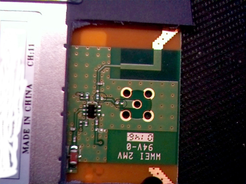
Here's a picture with the top off
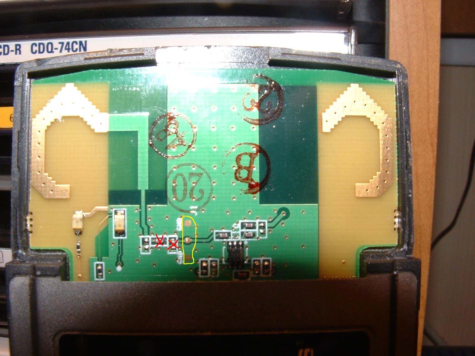
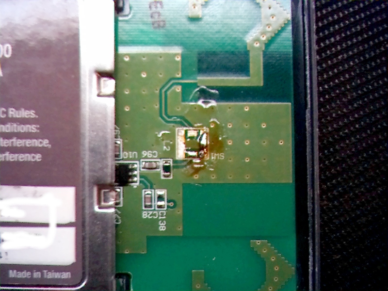
The back doesn't come off as easily, it's linked into the metal casing. Instead of bending up the metal I cut the plastic with the exacto. This needs to be done to move a couple of components on the board for the external connector.
There are two circles on the large image. The one with a component in it is a zero ohm resistor. This needs to be desoldered rotated 90 degrees and resoldered. The second circle has two pads that I think are going to need a cap for impedance matching. Haven't figured out what the value is yet so I'm just going to bridge it.
I just looked at a SMC card hack and it's exactly the same. No need to re-invent the wheel, follow their instructions. SMC hack
After hack
First you must pry the plastic cover open. This is pretty easy to do because there is only a light coating of glue holding the two halves together. Just put a flat head screw driver into the grove and twist as you work your way around.
Once you've split it open the bottom half needs to be eased out. Pull it up to about 15% and then ease it back and forth. It should come out without breaking and without damaging the metal around the pccard. The front doesn't need to come out.
I didn't take any pictures at this point but there are plenty of others on the web that show the card in this state of disassembly.
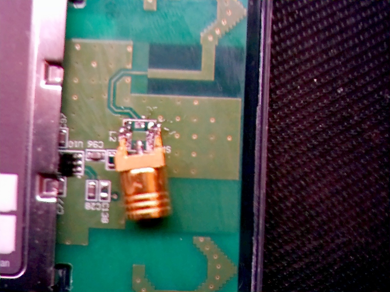
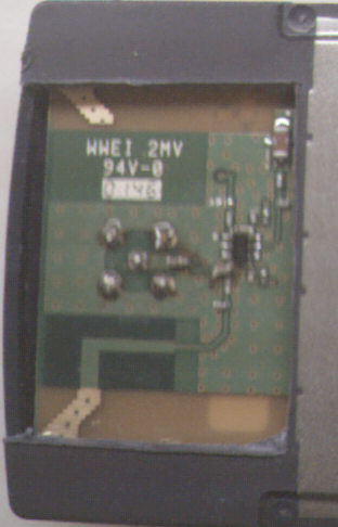
There is a little component on the board marked sw1. Doesn't look like any switch I've ever seen. This needs to come off. I did it by flowing a big bubble of solder under the component and sliding it off. Careful at this point so you don't pull the pads off the board. Here's a picture with sw1 removed.
Once you have sw1 off you need to find a connector. I used a female smb connector, but I think that a mmcx would probably be a better size. I mounted it on it's side to give it a little more strength. I still wouldn't trust appling to much pressure to it though.The center pin on my connector didn't bend well, ie. it broke, so I soldered a resistor lead coming straight out of the board and then attached the center lead to that.
Once you've got the connector on the board you might be tempted to check for shorts by measuring the resistance between the center pin and ground. When I tried this it didn't work. This is probably due to L1 being opaque to frequencies in the 2.4 Ghz range but not to DC. This is just a guess though, if you have a more plausible explanation send me email.
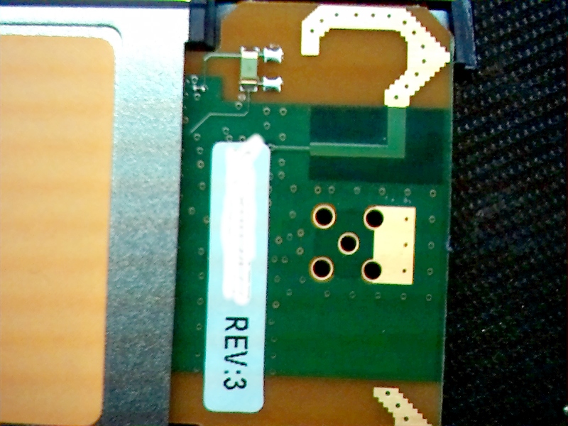
Below is a picture of the final product. If you try this send me some email and tell me how it went.